Kenwood TS-520S (1977–19xx)
Sixteen kilograms of hybrid HF transceiver built around a pair of S2001A finals and an analog dial that still rewards a steady hand.
Overview
The TS-520S has a solid-state front end and tubes in the final amplifier. Kenwood built this HF transceiver in Japan starting in 1977. The low-level stages are transistorized, but the part that puts RF into the antenna runs on glass. A 12BY7A driver feeds two S2001A final tubes. That hybrid layout gives quiet, cool-running reception on one hand and a tune-up ritual on the other.
Coverage runs from 160 through 10 meters across eight bands: 1.8-2.0, 3.5-4.0, 7.0-7.3, 14.0-14.35, 21.0-21.45, 28.0-28.5, 28.5-29.1, and 29.1-29.7 MHz, plus WWV at 15.0 MHz for receive only. Modes are SSB and CW. No FM, and no repeater shift. Period documentation states the design intent as SSB and CW operation across the 160-through-10-meter amateur bands, and nothing else.
Tuning is analog and continuous. There's no digital readout on the chassis itself. An accurate analog display handles frequency indication, and Kenwood sold the DG-5 external digital readout as an option for operators who wanted exact frequency display. That's the central compromise of the TS-520S.
Output is rated at approximately 100 W on both SSB (200 W PEP input) and CW (160 W DC input). Sensitivity is a claimed 0.25 µV for 10 dB signal-plus-noise-to-noise. Selectivity on SSB measures 2.4 kHz at -6 dB and 4.4 kHz at -60 dB. The CW side needs the optional YG-3395C filter to reach 500 Hz at -6 dB and 1.5 kHz at -60 dB. Image rejection is spec'd at 50 dB, and spurious emissions better than -40 dB.
Key Features
Hybrid Final Amplifier: 12BY7A Driver and Two S2001A Tubes
This is the single most important thing to know about owning one. Those tubes are the heart of the transmitter, they wear out, and replacing them is a documented rite of passage. The payoff is a final stage that behaves predictably and produces a clean signal when the bias and loading are set correctly.
Built-In Station Features
Period documentation notes that the TS-520S includes features "usually found as extras on other transceivers." The list backs that up. A noise blanker, a VOX circuit, a 25 kHz crystal calibrator, and phone patch connectors are all standard. There are also provisions for four crystal-controlled fixed channels. For a mid-priced HF rig of the late 1970s, that's a complete station in one box.
Analog Tuning and the DG-5 Option
The main tuning is continuous analog, with no synthesized steps and no memories. The DG-5 external digital readout was available as an option for operators who wanted exact frequency display. Frequency stability is quoted as within ±1 kHz during the first hour after a one-minute warm-up, tightening to within 100 Hz over any 30-minute period thereafter. So the radio wants a few minutes before you trust the dial.
Power Supply Flexibility: 120/220 VAC or 13.8 VDC
The TS-520S has a built-in mains supply, 120 or 220 VAC, and can also run from 13.8 VDC through a 12-pin connector for mobile or field use. Current draw is 5 A on receive with heaters on, dropping to 0.6 A with heaters off, and a maximum of 15 A on transmit at 13.8 VDC. The heater switch lets you listen with the tube heaters cold, which saves power for portable operation.
Antenna and Interconnect
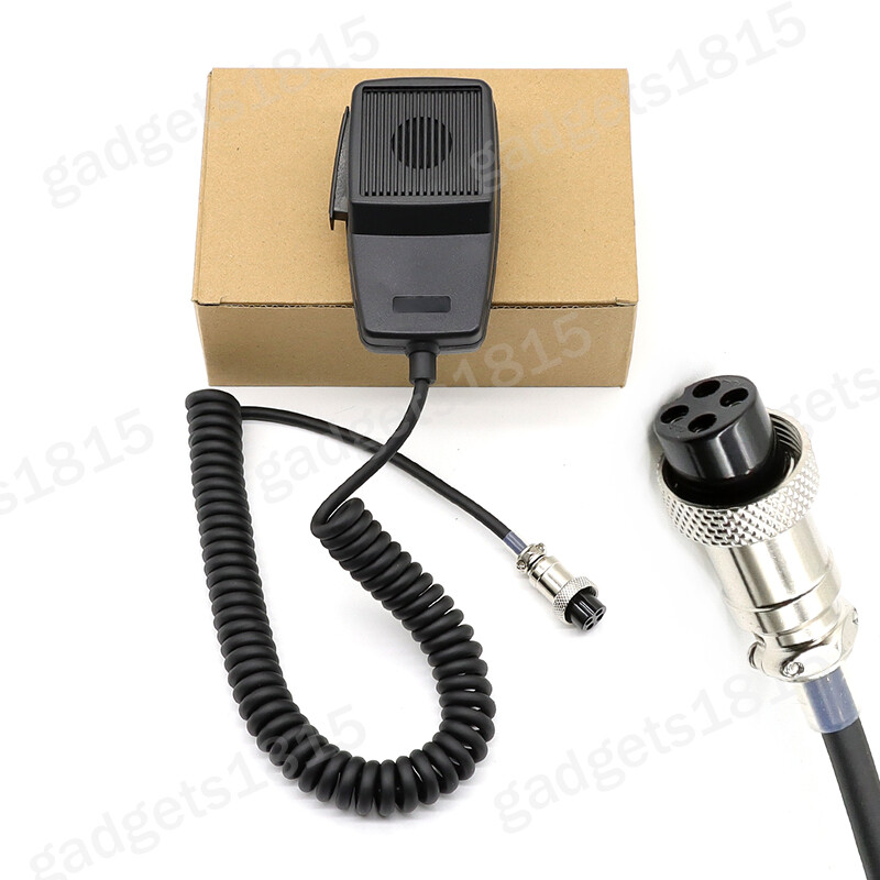
The antenna connection is a single SO-239, specified for 50-75 ohm feed. The pi-output matching network has some latitude, but this is not a forgiving radio on a bad antenna. Microphone input is high-impedance at 50 kOhm through a 4-pin metal locking-ring connector.
Historical Context
The TS-520S arrived in 1977. Production continued into the 1970s, though no source consulted for this archive states the exact end year. On price, one operator reports buying a TS-520S from HRO in 1978 for $649 delivered, which puts it in the serious-hobbyist bracket rather than the entry-level one. Another owner describes it as their first real radio, purchased after being licensed in 1974 but unable to afford equipment until 1978.
Collectibility & Value
The TS-520S has a durable following, and the reasons are practical. It's repairable, documented, and the failure points are known. The most commonly cited issues are burned-out pilot lamps and tired final tubes, and one owner notes needing both. Replacement lamps are available from at least one dedicated supplier, and the finals are a standard replacement job with multiple walkthroughs in circulation. The service manual runs 57 pages and addresses no-output, oscillator, RF, generator, final, and IF unit problems specifically.
Current market pricing is not well documented in the sources consulted. Listings for TS-520 series transceivers, restoration kits, and parts turn up regularly, and the radio shows up at hamfests in everything from neglected to restored condition. Buyers should expect to budget for lamps and possibly finals on any unit that hasn't been serviced. Original manuals sell separately, and one classified listing offered a complete original TS-520S manual for $15. A hi-res schematic is also in circulation.
eBay Listings



As an eBay Partner, we earn from qualifying purchases. This helps support our independent vintage technology research.